Why Does My 3D Scanner Keep Losing Tracking?
Quick answer: If your scanner repeatedly loses its position, the cause is usually a shortage of reliable visual references, an unsuitable surface, or a sudden change in the scan path. Work through these checks before rescanning the entire part.
Practical guide for industrial scanning and optical metrology.
Check the scanner's tracking mode
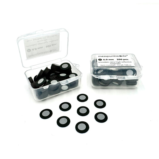
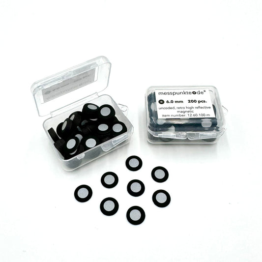
Confirm whether the active mode uses geometry, texture, or reference markers. Featureless cylinders, large flat panels, and repeating patterns often defeat geometry tracking. In marker mode, verify that the software recognizes the target type and diameter.
Maintain marker overlap
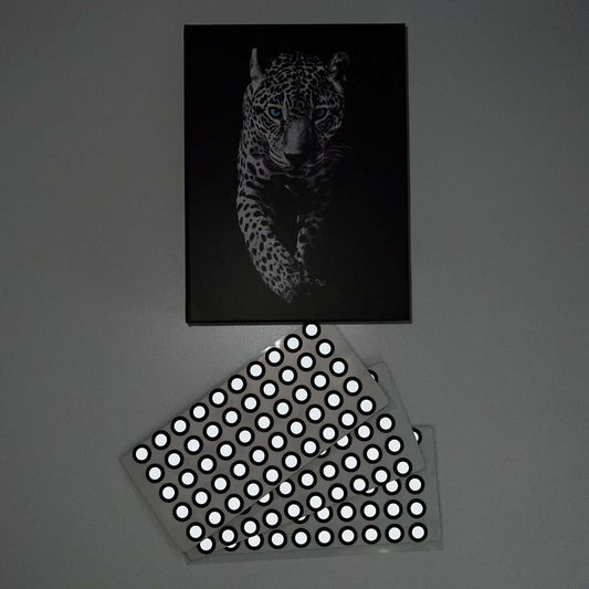
Keep the minimum number of markers required by your scanner visible as you move; for many handheld marker-tracking systems, roughly five or more visible targets is a useful starting point, not a universal specification. Place them irregularly, with sufficient overlap between adjacent views. Avoid straight rows and symmetrical patterns.
Check the surface and standoff
Black, glossy, chrome, and transparent parts can produce weak or misleading optical signals. Adjust exposure or scanning mode first. When needed, use a compatible, thin matte coating. Stay within the scanner's indicated working distance and move smoothly.
Recover without introducing drift
Return to the last well-tracked area, let the software recover, then continue slowly. If the scan keeps drifting, stop and inspect target movement, scanner calibration, and whether the fixture or part shifted during capture.
Verify the result
Check a known dimension or reference artifact before accepting dimensional data. A smooth-looking mesh is not proof of measurement accuracy.
Related 3D scanning guides
If your scan still slips, check how many reference dots stay visible, how target-dot placement affects tracking, and whether your scanner requires targets. These articles cover the next steps in the same workflow.
Frequently asked questions
Can extra markers fix tracking loss?
Only if poor marker coverage was the cause. Incorrect target size, poor contrast, part motion, and calibration problems still need correction.
Do I need targets on the part?
Not always. A rigid fixture or surrounding marker frame can work when it remains stationary relative to the object and is supported by the scanner workflow.
Next step: View relevant 3D scanning supplies and technical guidance. For target compatibility and chemical handling, verify the manufacturer's current documentation.
How we select and verify technical sources ↗
Technical guidance is general. Check your scanner documentation and the relevant manufacturer's current technical and safety data sheets before applying products to sensitive parts.